
Hardware#
A 3D-rendering of the table can be seen below. The basic hardware components of the shaking table are an aluminum frame, linear rails, linear bearings, the plate, the motor with its driver and the driving assembly, as well as the necessary electrical components. Each component is described in this section and some details on their functionality are given. Since different choices can be made for each part we also give some comments about possible variants.
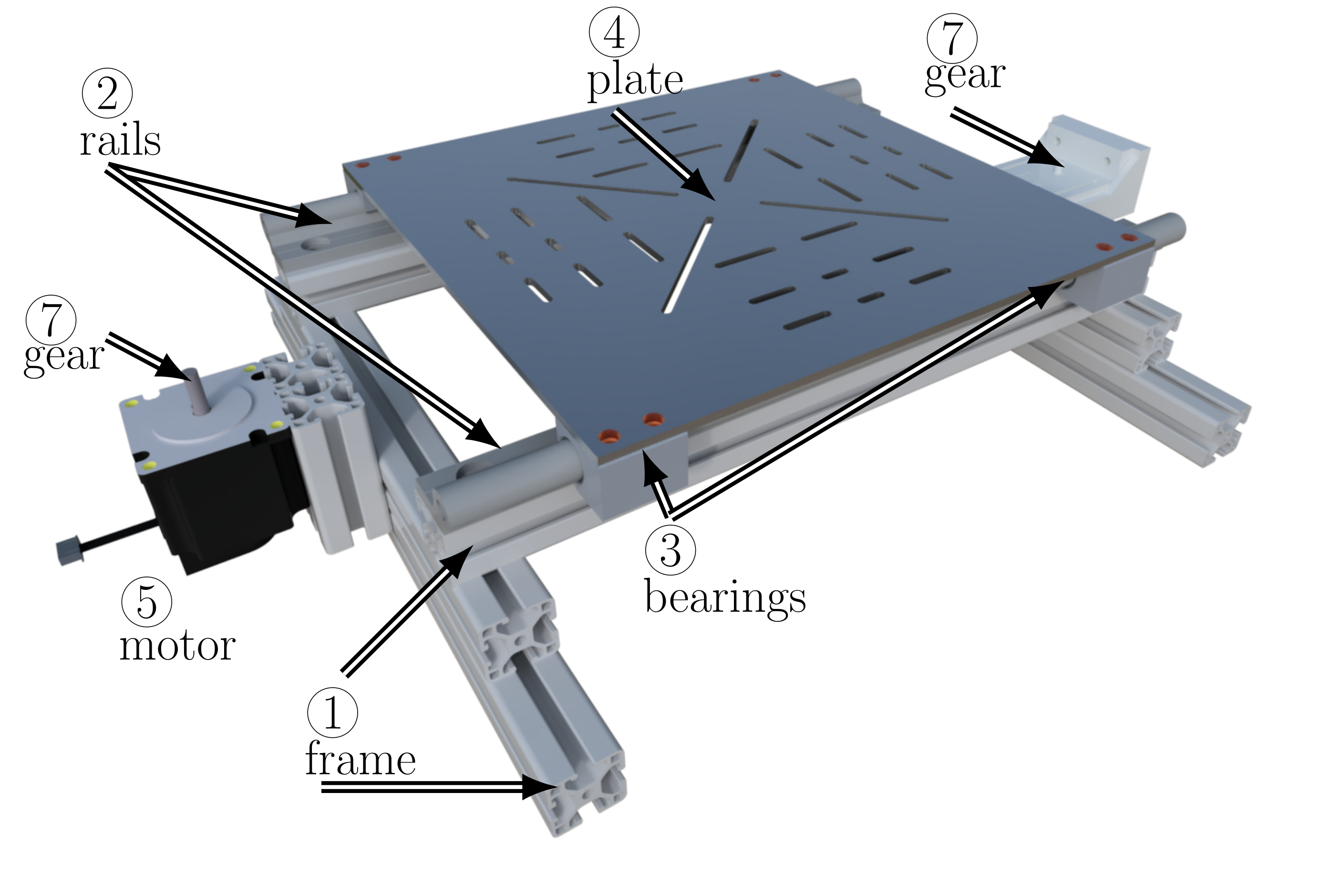
3D rendering of the table CAD files.#
A technical drawing with dimensions is shown below. The mass of the table is \({6.80}\, \text{kg}\). Its footprint is about \({400}\, \text{mm}\times {500}\, \text{mm}\) and it takes one person about one hour to fully assemble it. This table gives a list of hardware components and the associated costs. Tested properties obtained with Namazu are:
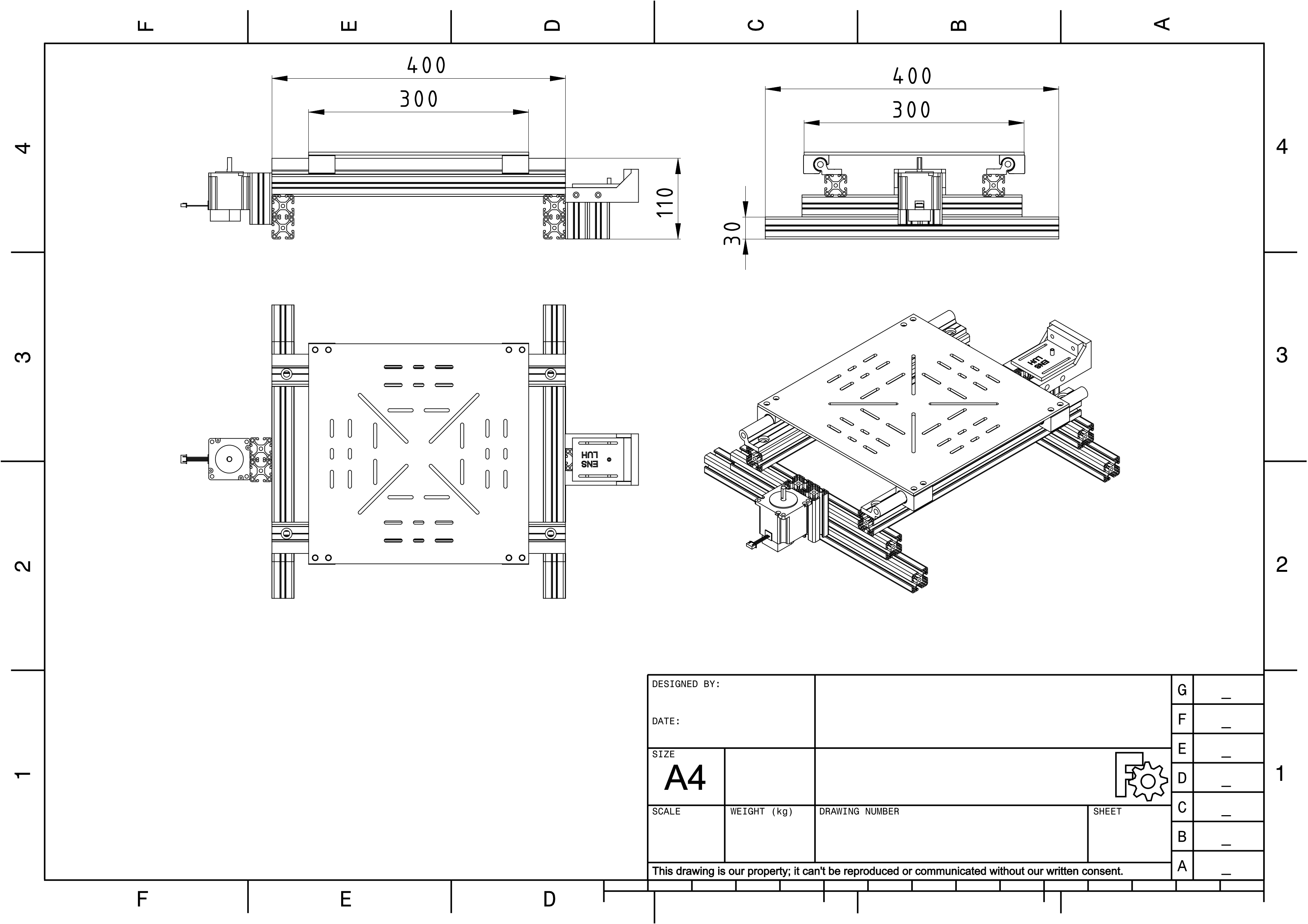
Technical drawing of the table, dimensions in millimeters.#
Nr. |
Hardware |
Description |
Price |
|---|---|---|---|
1 |
Frame |
30x30 I-Type aluminium extrusions (4x 400 mm, 2x 300 mm, 4x 70 mm) |
21.64€ |
2 |
Linear rails |
igus drylin W, WS16_0.4M |
31.74€ |
3 |
Linear bearings |
igus drylin W, WJ2000UME-01-16 |
41.48€ |
4 |
Plate |
300x300x4 aluminium plate |
42.69€ |
5 |
Motor |
NEMA23 (ACT 23HS8430D8P1) |
21.60€ |
6 |
Driver |
ACT DM542 |
33.10€ |
7 |
Gears |
GT-2, 20 teeth gear and idler |
5.00€ |
8 |
Belt |
GT-2, 1m |
4.99€ |
9 |
Power supply |
PEAKTECH 6227 |
123.17€ |
10 |
Microcontroller |
NodeMCU ESP32-WROOM32 |
11.49€ |
Misc. |
Attachment plates, screws, nuts, etc. (price is an estimate) |
60.00€ |
|
Total: |
396.90€ |
Frame and rails#
The frame is made up of standard \({30}\, \text{mm} \times {30}\, \text{mm}\) I-Type aluminum extrusions. They make assembly and disassembly of the table very practical, and allow for flexibility in the design, since hardware components can be mounted anywhere the user desires. The plate is designed with different mounting holes for mounting a large variety of mock-up specimens. The plate is attached to the frame by two low-maintenance friction bearings and rails (igus drylinW). The frame has to be fixed to some object with high mass to avoid vibrations of the surroundings, e.g., it can be bolted to a rigid high-mass table.
Motor and driver#
The displacement is applied to the plate by a bipolar stepper motor through a belt-gear system. Bipolar stepper motors are made up of two sets of coils. By switching the current through the coils and, therefore, the polarity of the induced magnetic fields, the motor is forced to turn by one step. The motor driver is a specialized electronic circuit, which handles the necessary operations for the electrical current output to realize this careful switching. It acts as an interface between the controller and the motor.
Under ideal circumstances, the position of a stepper motor is known at all times, and a feedback loop is not needed. The setup is thus cost-effective and overall simple. In addition, the driver is able to perform so-called microsteps which enable the motor to be set to positions that do not correspond to full steps. This is achieved by interpolating the coil current. Using microsteps enhances the resolution of the motor without changing the hardware components. It also increases the versatility of the setup.
An important characteristic of the table is the number of steps \(n_{/disp}\) that the motor performs for a given displacement, often taken as the number of steps per millimeter. This characteristic depends on the motor, the microstep setting and the hardware, i.e. the driving components. It can be calculated from the number of steps the motor performs per revolution and the displacement of the plate during one revolution of the motor as follows
The current setup uses a NEMA23 motor, where the coils are \(1.8^{\circ}\) apart. The DM542-driver is set to a microstep setting of 32 microsteps between two coils, so 6,400 . The belt comprises a tooth every 2 mm, and the GT2 gear has 20 teeth in total, so the belt moves by \(40\) . Therefore, the resolution of the Namazu setup with the features detailed here is \(n_{/disp}=160\) steps per millimeter; one microstep corresponds to a displacement of \({0.0063}\, \text{mm}\). This feature is directly set via a serial command to the motor without the need to reprogram the controller.
For stepper motors, a trade-off has to be accepted between speed and available torque. More microsteps per revolution decrease the available torque and also slightly decrease the accuracy, since the driver needs to interpolate the coil current between two full steps. Indeed, with high speeds the driver has less time to switch the coil current between steps and the inertia of the payload and the table assembly can perturb the control. If the motor torque is not adequate for the applied loads, it can result in loss of steps and therefore loss of accuracy. Nevertheless, there are many different sizes of motors available with torque ratings ranging from as low as a few \(\text{Ncm}\) (e.g. NEMA 11) to large motors capable of achieving a few tens of \(\text{Nm}\) (e.g. NEMA 42). A similar comment can be made about the microstep setting. Another remedy is planetary gearboxes with different ratios available for various motors. The planetary gearboxes increase the resolution without the need for microsteps. The drawback is that the gearboxes usually introduce some backlash, and the ratios are not adjustable.
Microcontroller#
The microcontroller is the core element of the Namazu control
structure. It is the interfacing element between the hardware (driver)
and software, which sets the motor velocity and rotation direction as
well as storing, starting and stopping of an experiment. A desired
displacement signal can be uploaded to the controller via the serial
interface. Once the experiment is started, the controller pulses the
STEP-pin of the motor driver at a certain frequency that depends on
the desired speed, which in turn is dependent on the desired
displacement. These calculations are performed by the microcontroller
and stored before the experiment. For each STEP-pulse the motor
turns by one step, i.e. changing the frequency of the pulse allows for
the definition of arbitrary signals, which is the core functionality of
Namazu.
The compatibility of the microcontroller with the free real-time operating system (FreeRTOS) and the Arduino framework is mandatory to use the provided program. Further, we recommend a high-resolution hardware timer for the microcontroller such that the motor is controlled with high precision. The chosen microcontroller is an ESP32 devkit module. The processors’ clock rate of \(250\, \text{MHz}\) empowers us to update the motors’ velocity and direction of rotation up to \(200\) times per second. Moreover, the ESP32 provides a second core that can handle interrupts and provide a control interface, without interfering with the motor’s update rate. Thereby, we isolate the experiment from interfacing operations and improve the repeatability of experiments.
Variants#
The Namazu shaking table that is presented here comprises various pieces, which could be upgraded/downgraded independently depending on the user’s budget and research needs. This makes the shaking-table tunable. Indeed, it can be personalized to fit desired accuracy or operational conditions. Some variants are exposed in 2. Note that variations in the hardware make it necessary to recalculate the steps per mm setting for the motor, as this property depends on the physical properties of the table as well as the microstep settings in the driver. As an example, changing the belt and gear assembly of the current setup to a \(1610\) ball screw assembly (\(1610\) referring to a screw diameter of \({16}\, \text{mm}\) and a screw lead of \({10}\, \text{mm}\)) means that the belt, and so the table, is moved by \({10}\, \text{mm}\) per revolution of the motor. Together with the \(200\) steps per revolution of the motor this leads to a resolution of the shaking table of \(n_{/disp}\) equal to \(20\) steps per \(\text{mm}\).
Most limitations on payload capacity, acceleration, and speed are only given by the hardware components. Here, tests have shown that the Namazu table with current components performs well with physical properties given in [eq:PhysProp]. The tested payload is \({2}\, \text{kg}\). This small payload can fit some research projects. Besides, for teaching purposes, we find that using the table in combination with 3D-printed structures offers a versatile and low-cost solution to give students some experience with designing and testing parts. Indeed, 3D-printed structures, when printed with materials such as polylactic acid (PLA) or thermoplastic polyurethane (TPU), are cheep and lightweight. Therefore, a low-torque motor as introduced here can achieve already satisfying accuracy, with low cost hardware and simple handling of the Namazu framework. As a reference, the payload limitations on the SARSAR shaking table [1] are given as \({200}\, \text{kg}\) capacity while also using a (more capable) stepper motor and a ball screw instead of the belt gear driving system.
Original piece |
Upgraded piece |
Advantage |
Belt & gear assembly |
Trapezoidal screw |
Higher accuracy and payload capabilities, more rigid construction due to no flexible parts, no inaccuracies due to belt slipping |
Ball screw |
Even higher accuracy and payload capabilities, smoother operation than trapezoidal screws, no inaccuracies due to belt slipping |
|
Friction bearings |
Roller bearings (SBR16UU etc.) |
Higher payload capabilities |
Frame |
Pre-built linear positioning table |
Higher manufacturing accuracy, multiple variants available |
NEMA23 motor, DM542 driver |
NEMA34 motor, DM860T driver |
Higher torque, higher payload |
The table can also be tuned to decrease the cost. A motor with a lower torque such as the NEMA17 motor could be employed. These motors are very common since they are a standard parts used in 3D printers. There exists a wide variety of motor and driver combinations, thus we can not provide a comprehensive list. 1 shows that the highest cost in the setup comes from the power supply. We use here an adjustable power supply. It could be changed by a fixed voltage power supply to save cost.
Hardware interface#
Warning
These functionalities are currently under development and should be used with caution.
We implemented an option to connect buttons and limit switches to the table. The buttons can be used to enhance the functionality as they provide a direct way of starting and stopping the experiments, as well as moving the table to a desired position and centering the table in the middle position. The limit switches provide an additional safety mechanism and are also necessary to center the table.