
Build instructions#
The present document shows the assembly of the table as it was put together in the IRTG/IRZ/IBNM-lab at the University of Hannover in June 2023. Note that the actual assembly of the frame might not be the most optimal, as it was observed that some parts of the frame could move and shift during operation. It might be possible to stiffen up the assembly by additional parts or by assembling the table in a different way altogether. The present document provides only a suggestion of assembly.
We kept the setup of all components (frame, motor, electronics) as general as possible, so that this framework should work with different setups. In our version we used a belt and gears together with a NEMA23 stepper motor to drive the table, but it should be possible to use other parts, i.e. other stepper motors or ball/trapezoidal screws for the driving mechanism. The software works by controlling the stepping rate of the motor, so theoretically any stepper motor/controller should work (we tested this set up so far with a NEMA23 motor and a DM542 driver, as well as a NEMA17 with TMC2209 and A4988 driver).
Assembly of the table#
This section describes the assembly of the table. For further details and explanations on hardware components please see the Hardware section, for software the Software section and for a quick overview the Usage section.
Assembly of the frame#
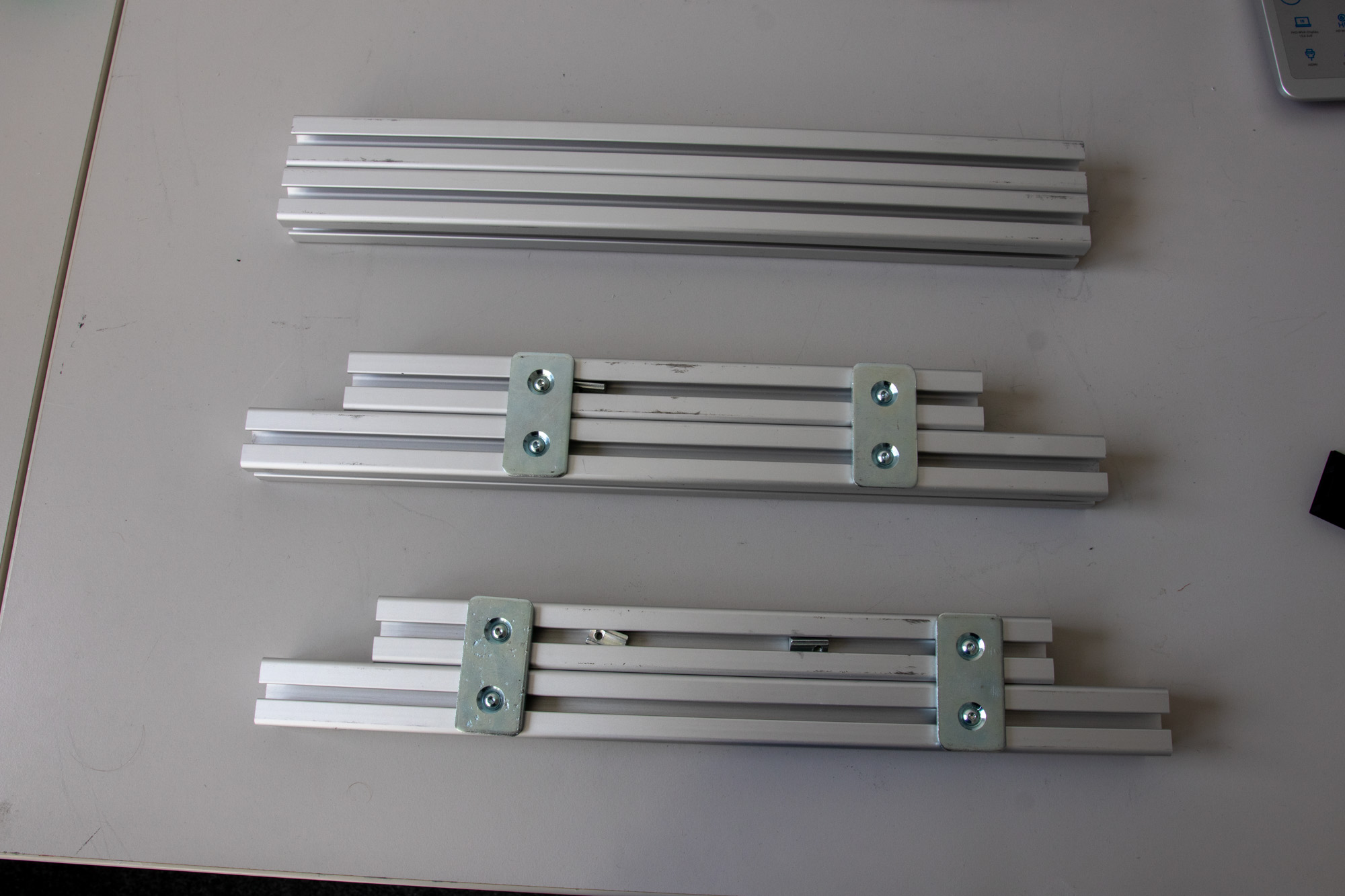
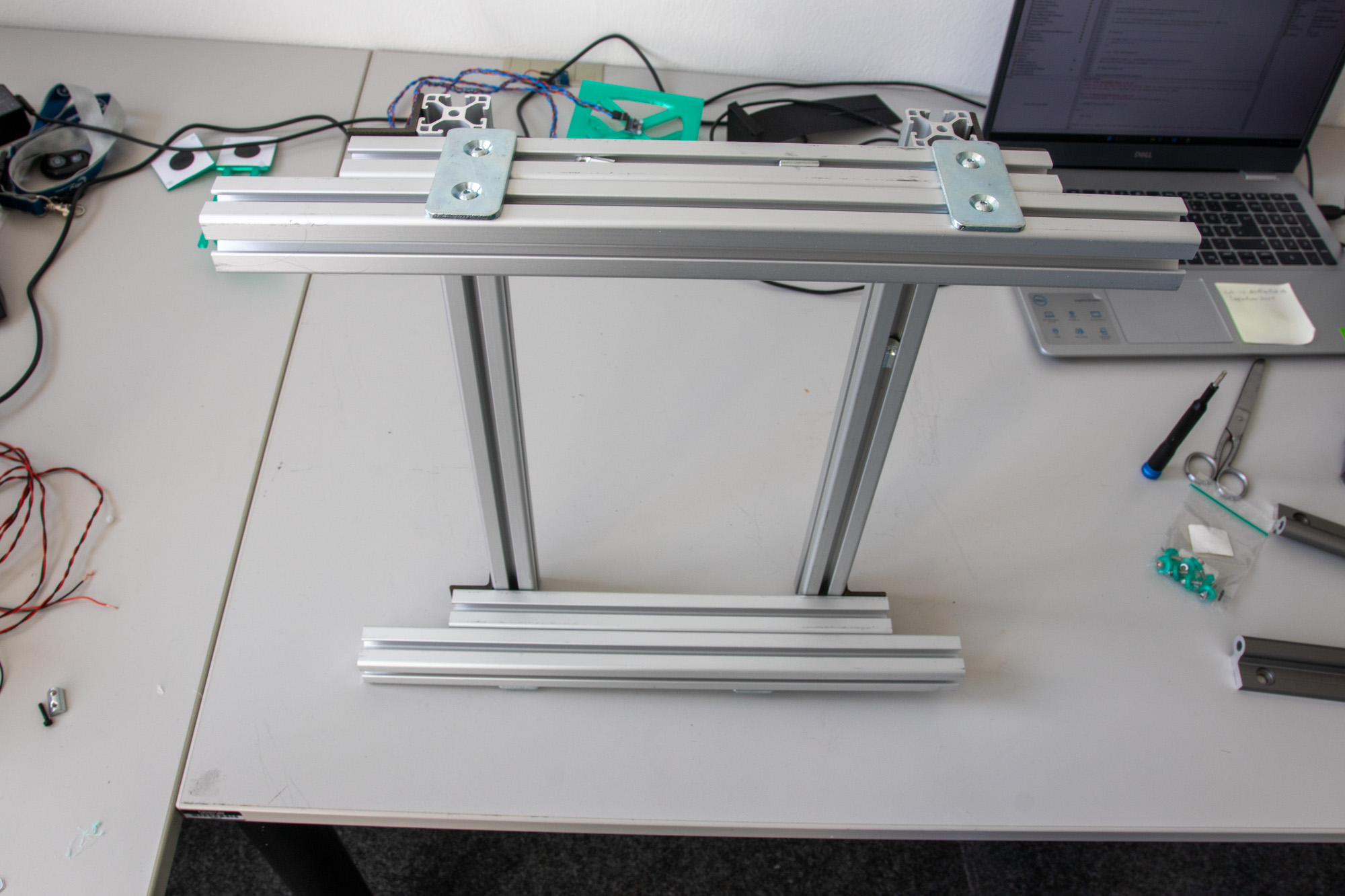
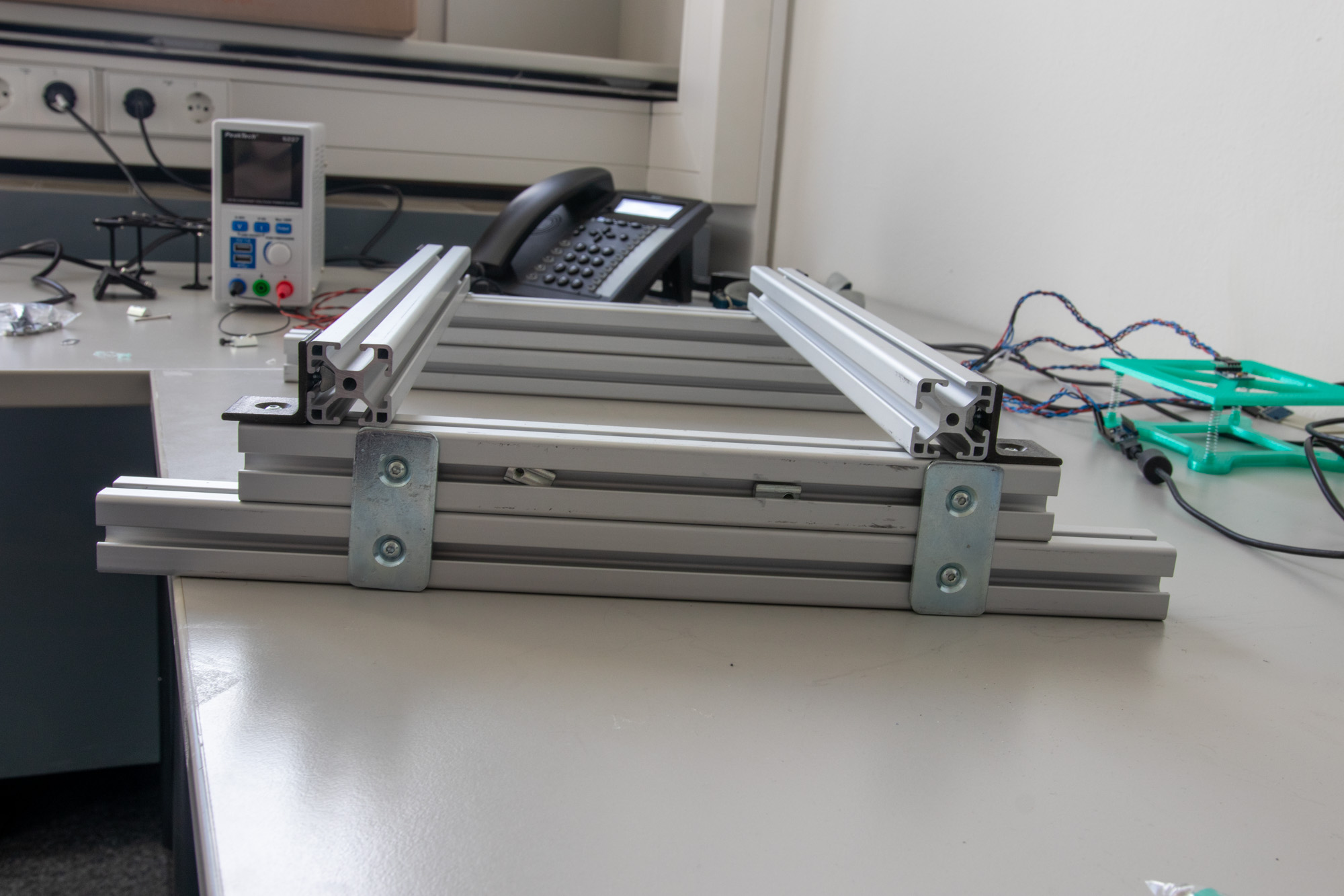
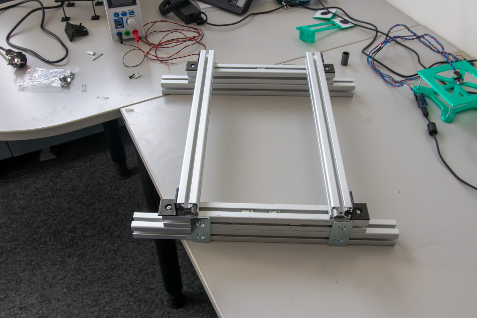
The frame consists of the aluminium extrusions, screws with T-nuts, 90° angles and connector plates. We used two of the 400mm parts as supports for the rails and an assembly of one 300mm and one 400mm part as stands, as shown here. Leave eight empty threaded sockets on each side (2 outer sides and 2 upwards sides) in between the fix of the 300mm and 400mm frame parts, these threads are later used for the e-motor and the gear of the v-belt. The height of the frame itself is therefore 90 mm, which is actually needed since the motor is somewhat tall. A downside of this assembly is that there is no cross-bracing, meaning the assembly can shift a bit. Furthermore, it is somewhat hard to actually line up the rails correctly such that they are parallel, which can lead to excess friction and vibrations. So far we did not come up with a good solution here.
The two 400mm parts are screwed in to the top of the stands using the 90° angles. It might be a good idea to also screw down the inner parts of these with 90° angles for more rigidity. Note however that adjusting the rails later on is then difficult since the plate will be in the way.
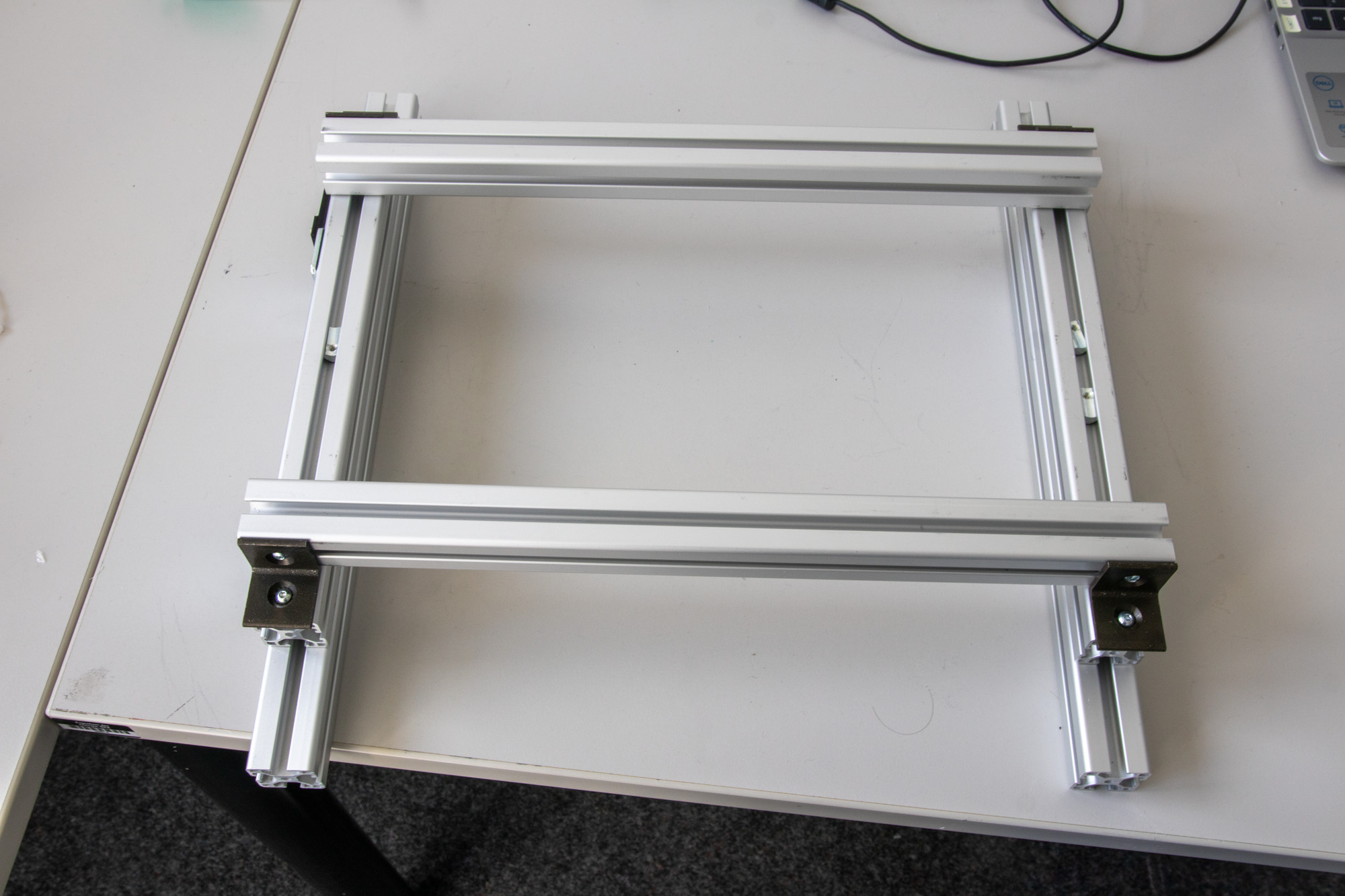
The rails can be screwed in on top of the frame using the M4x12 screws and the 3D-printed washers. I forgot to take pictures of the assembly with only the rails installed..
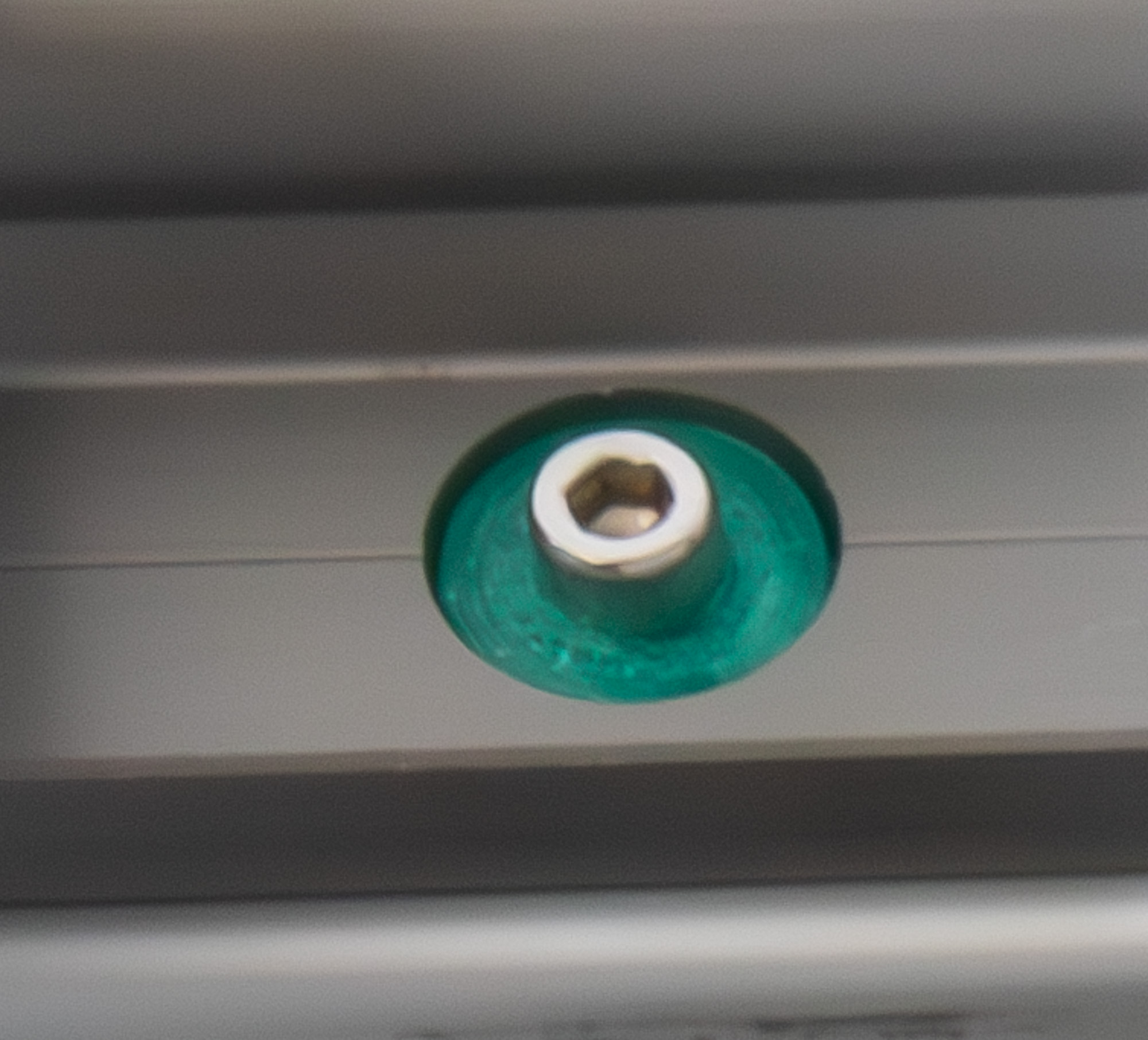
Screws with washers for the rails#
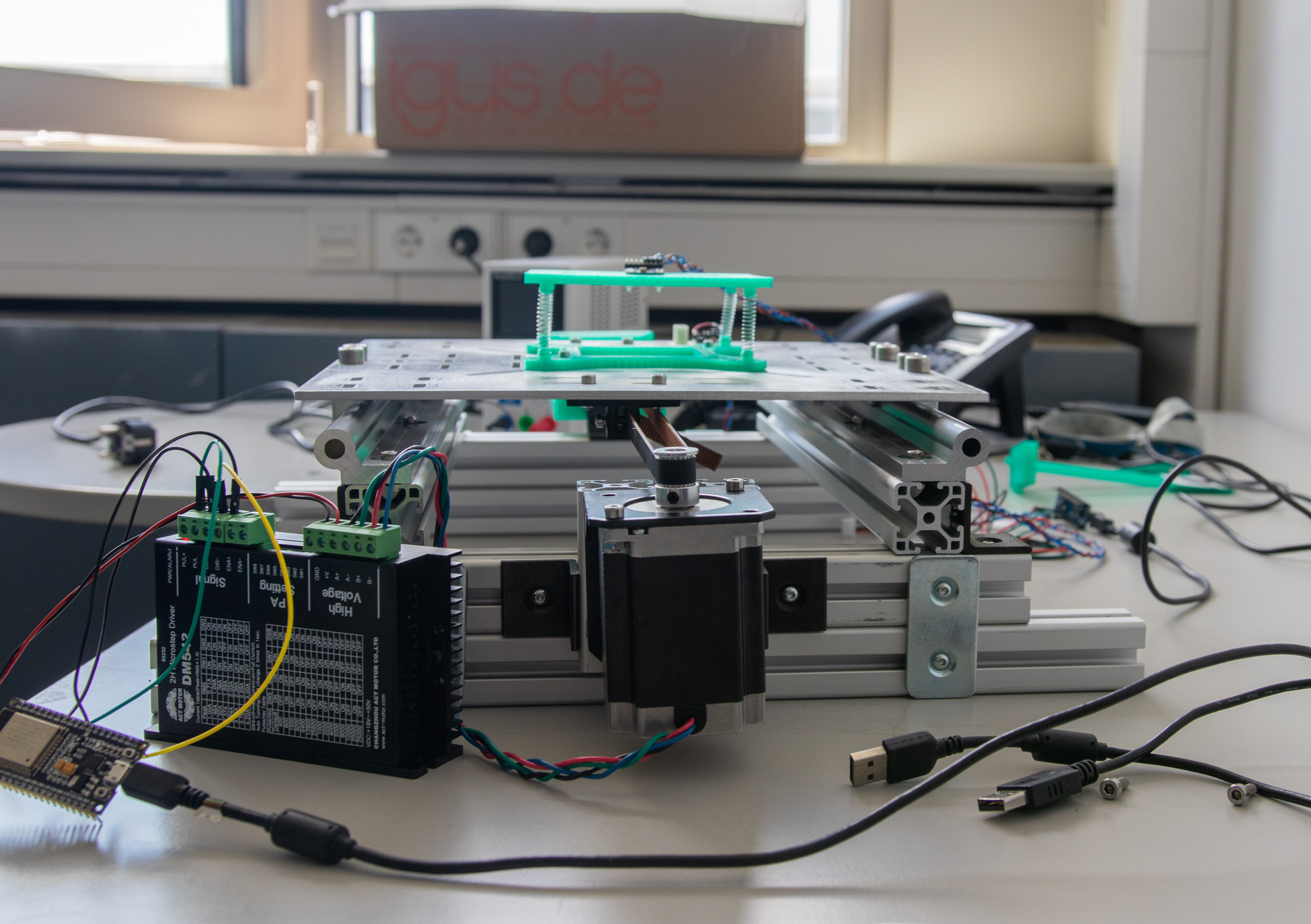
Assembly of the motor#
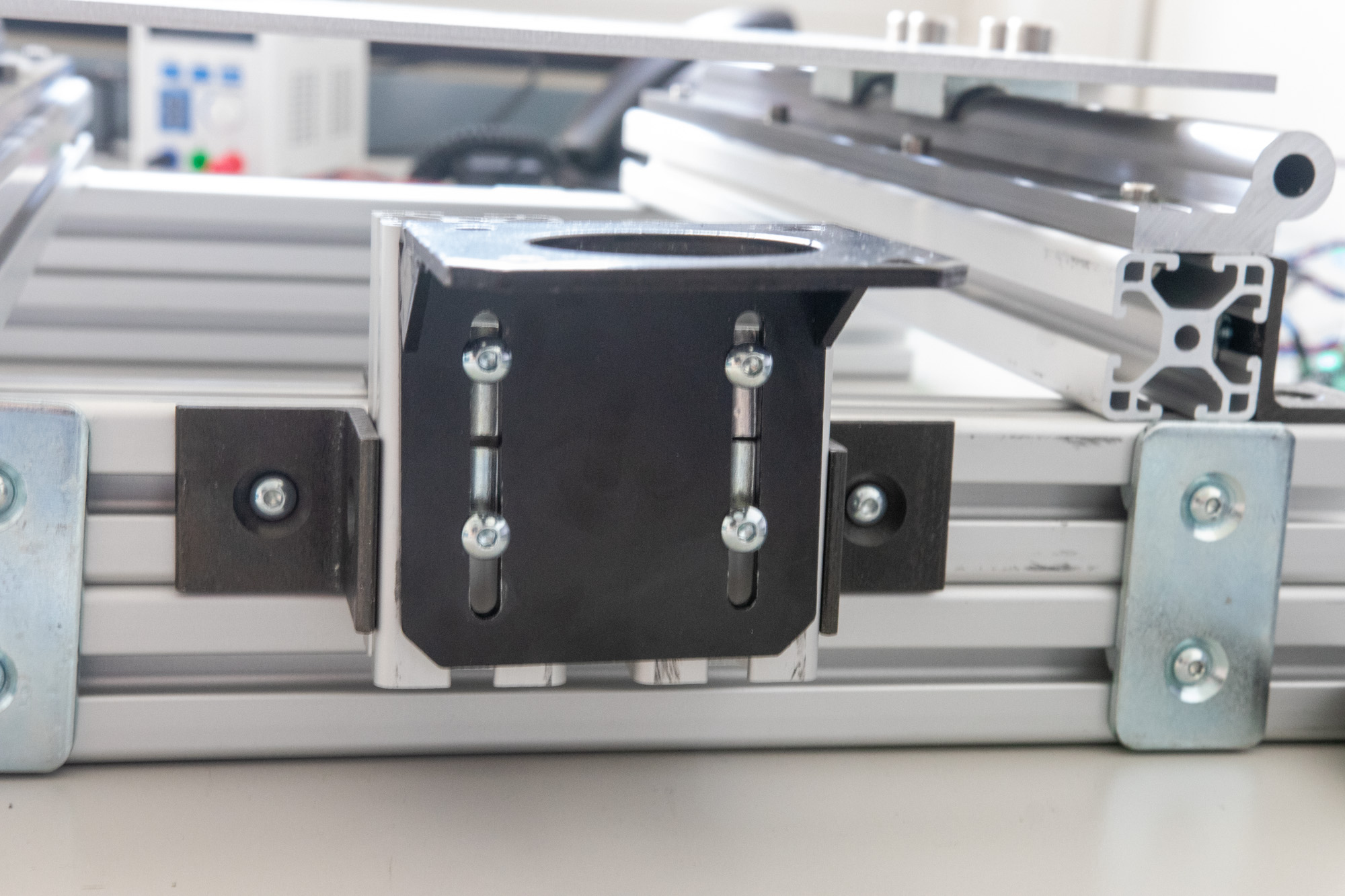
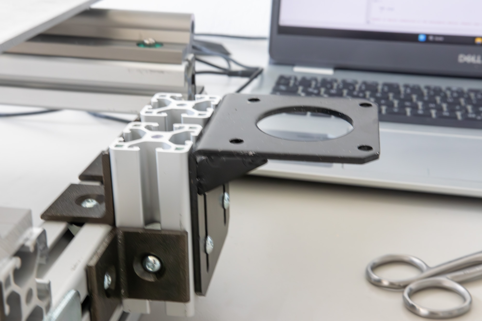
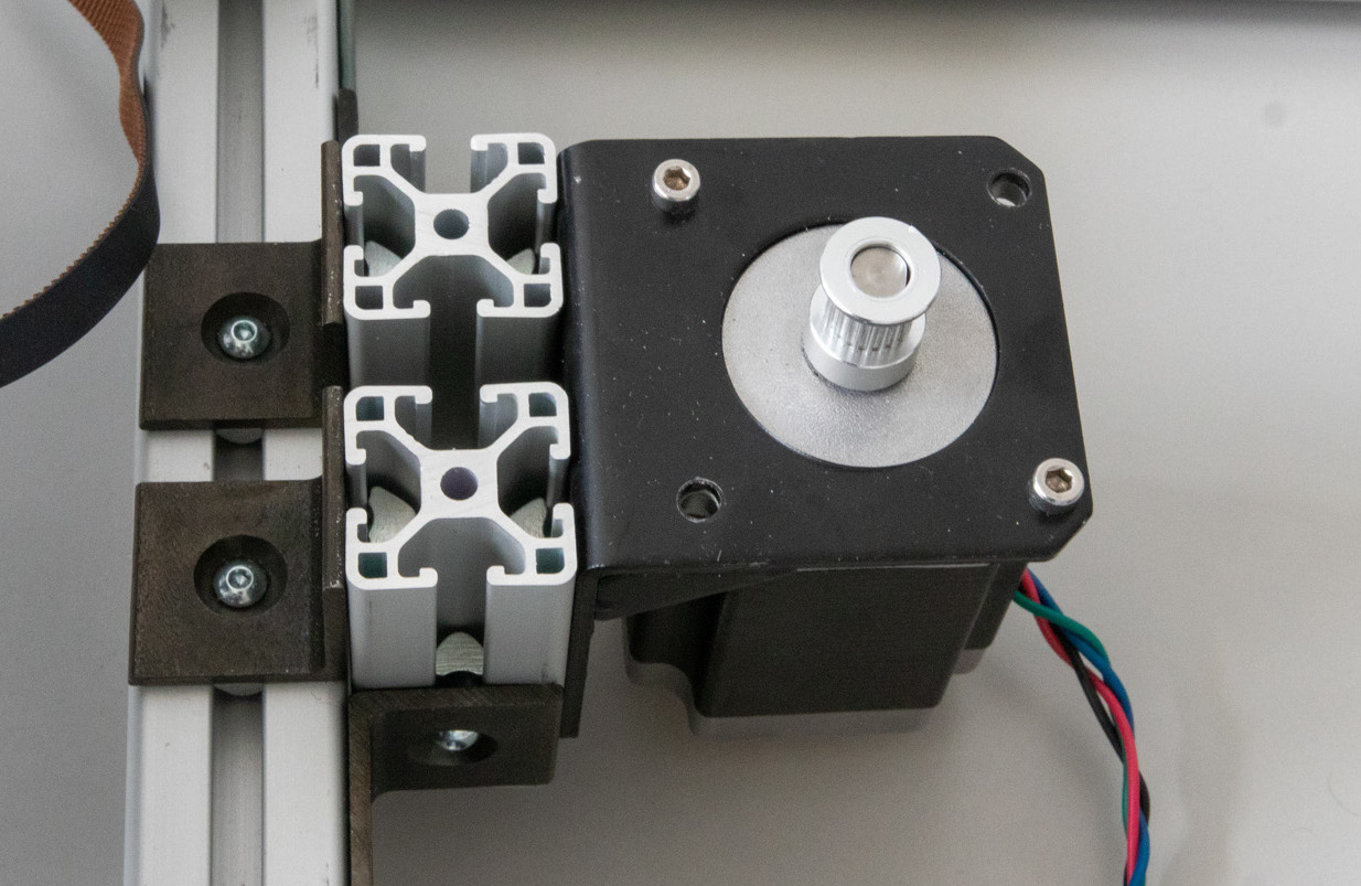
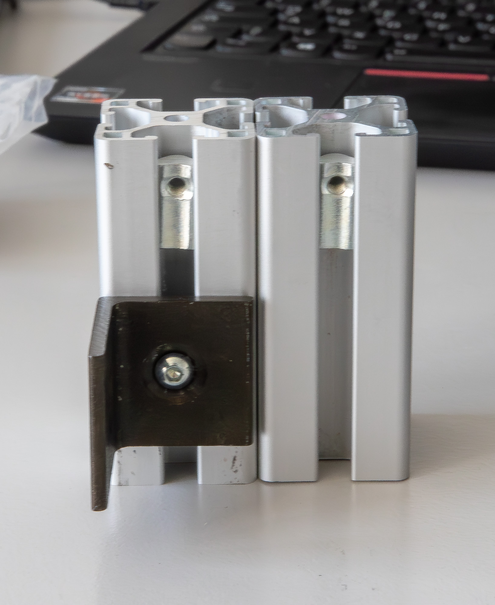
The motor attachment assembly consists of two 70 mm aluminium extrusions, four 90° angles and the NEMA23 attachment bracket. The bracket is screwed into the extrusions with four screws and attached to the frame using the angles as shown in the pictures.
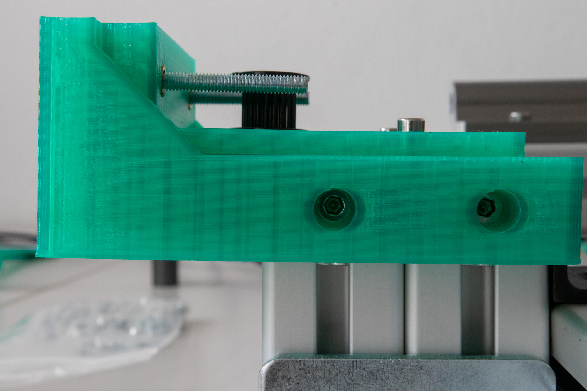
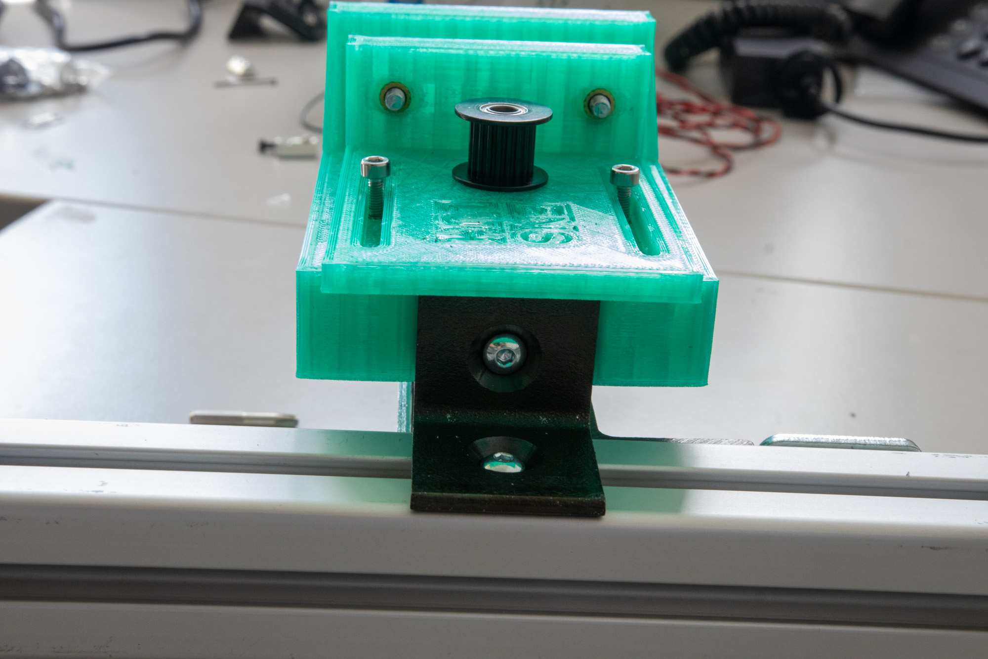
Assembly of the belt tensioner#
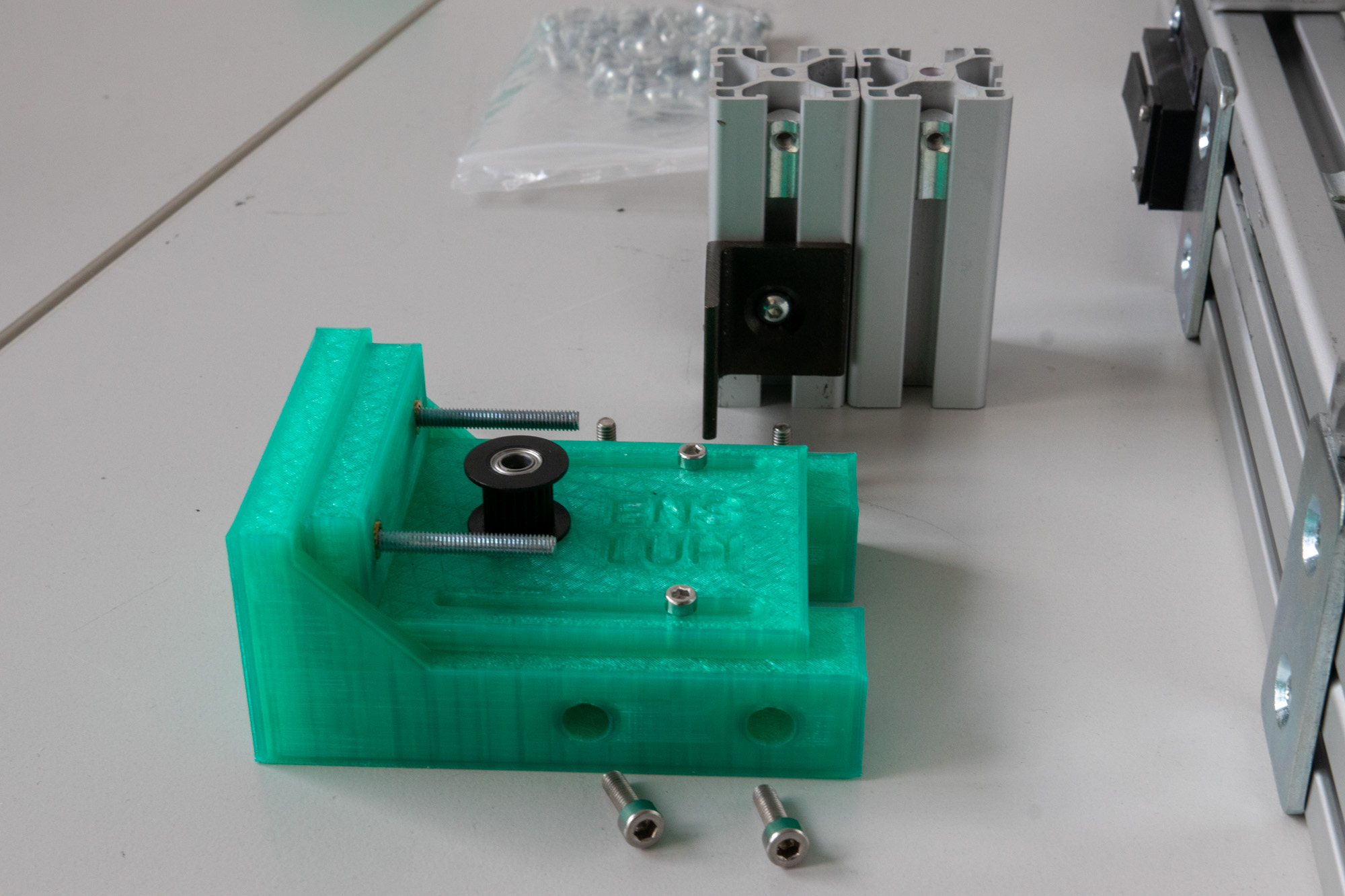
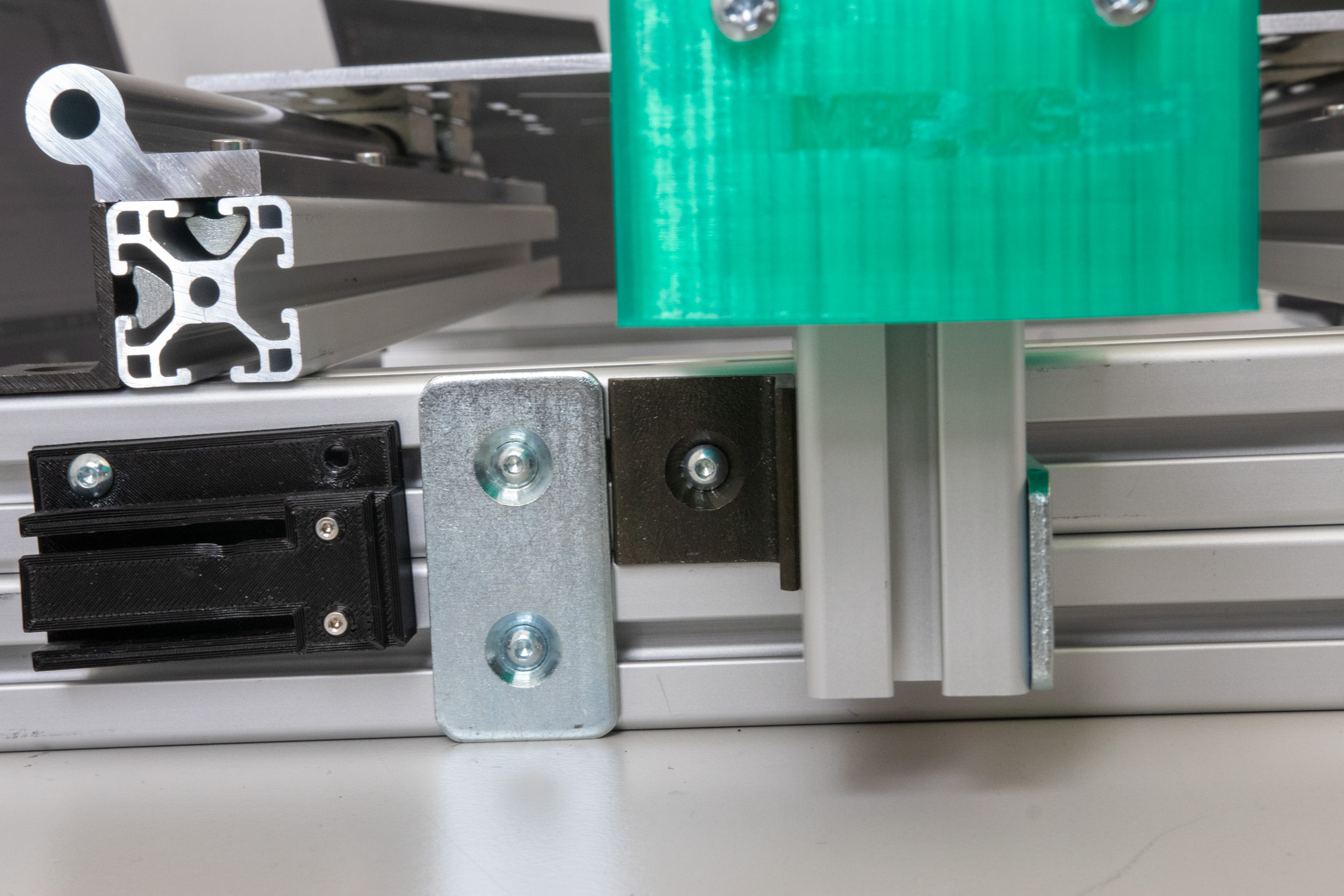
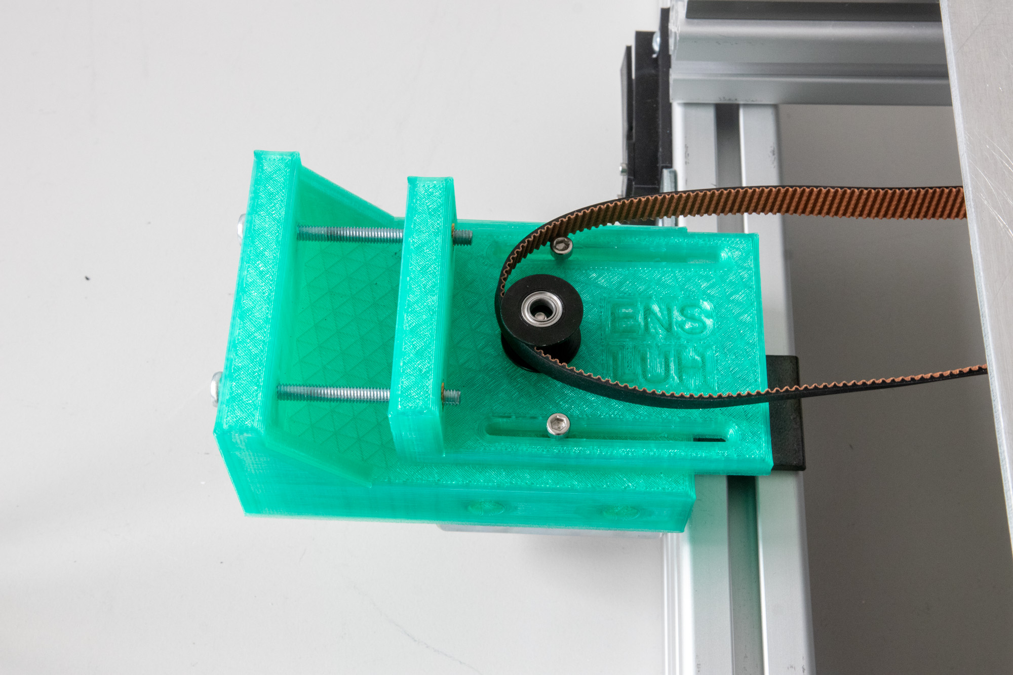
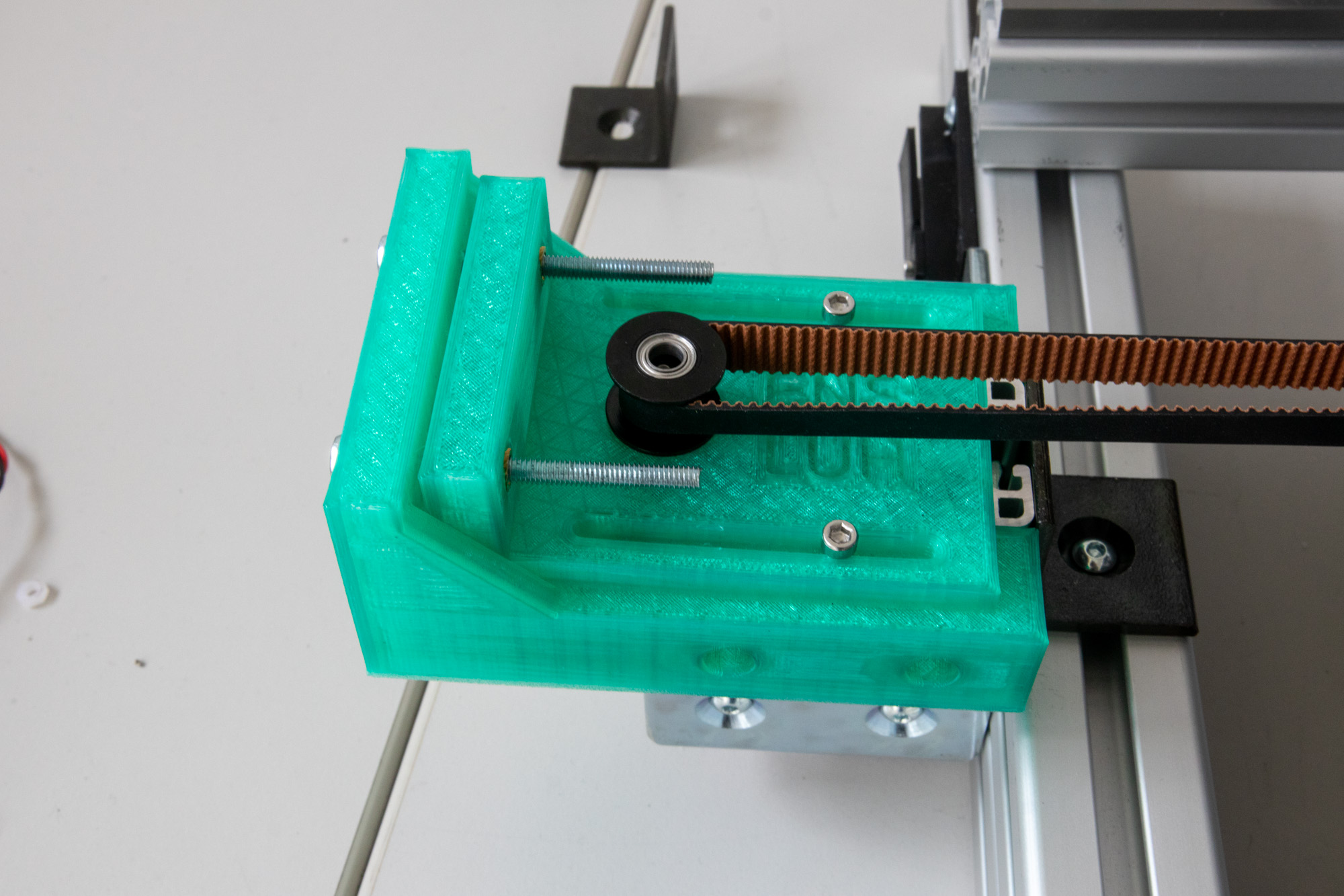
This assembly is used to tension the belt (as the name suggests). It consists of two 70mm aluminium extrusions, a connector plate, angles and the 3D-printed tensioner itself. The two extrusions are connected with the connector plate and screwed in on the short side with a 90° angle. For rigidity reasons we used another angle to screw it in the top part of the frame stand (see here). The 3D-printed part should slide on top of the extrusions and can be attached with T-nuts and M4x12 screws from the sides (see here).
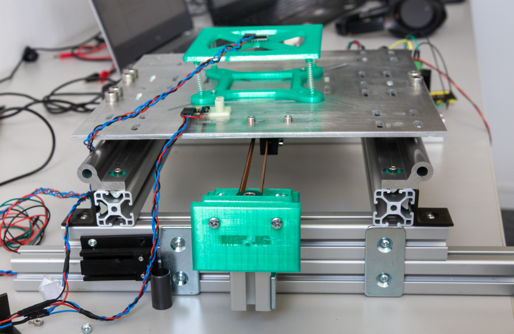
Belt#
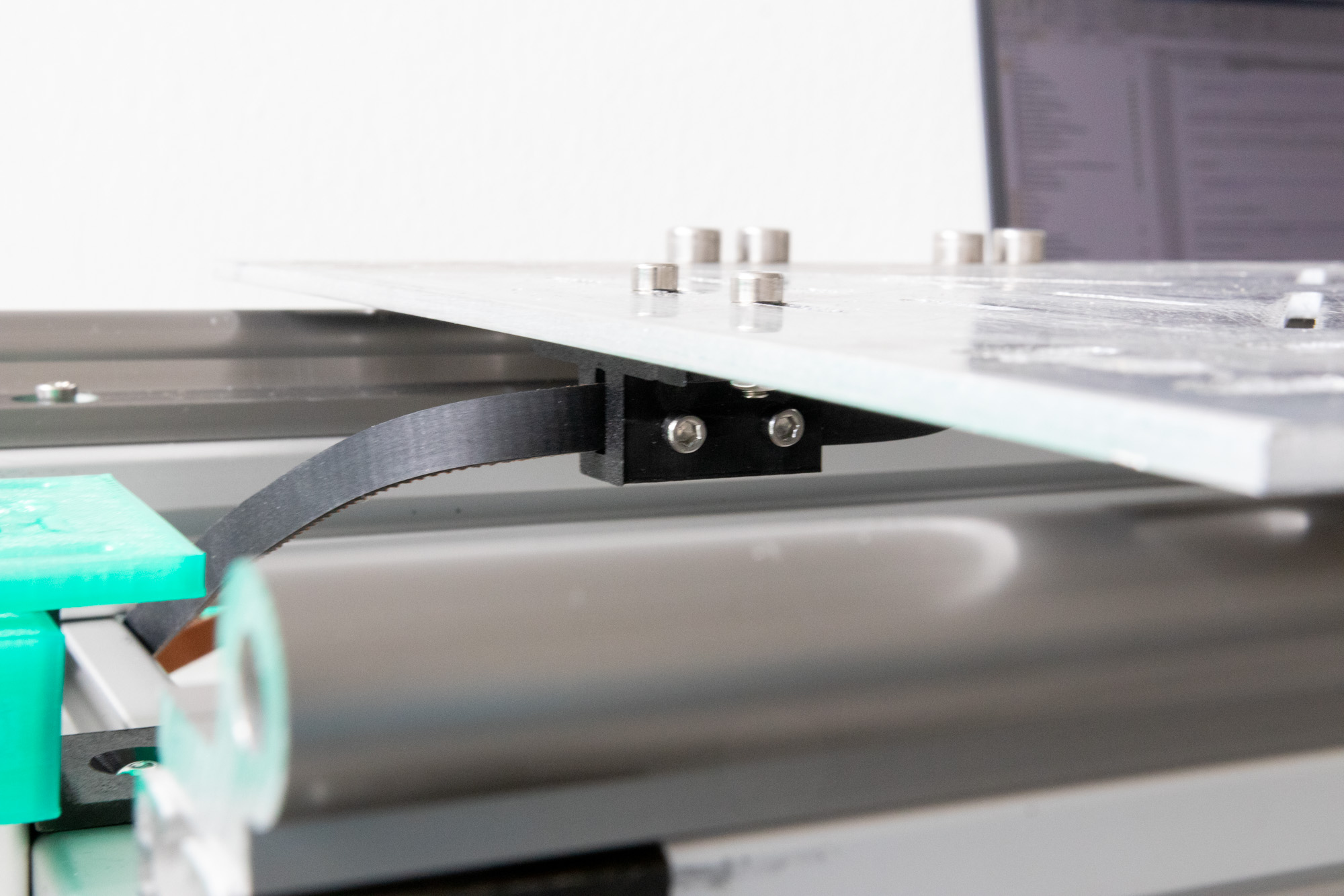
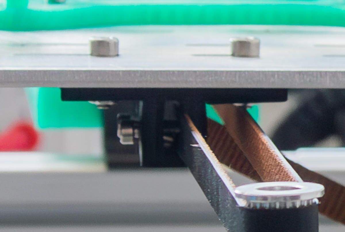
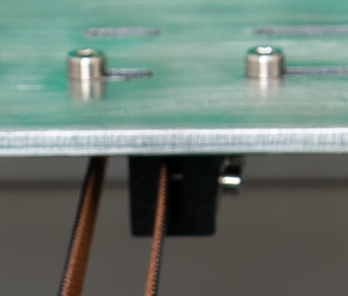
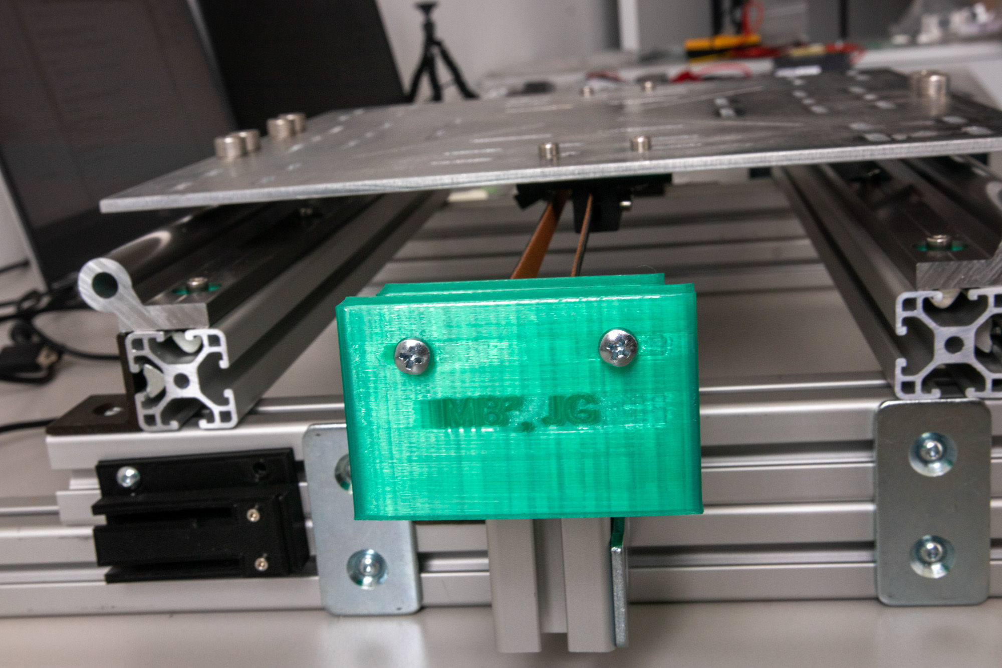
The 3D-printed belt holders are screwed into the plate using M4x12 screws and nuts. The belt can then be inserted into these and fastened with M3 screws from the side. Note that in order to screw in these screws, there are M3-nuts on the inside with a small recess so they don’t turn while turning the screw. If the screw is pushed too much they can jump out of this recess and it is not possible to fasten the belt. Just pull on the screw a bit until the nut is recessed again if that happens. It is also difficult to reach these screws while the plate is attached to the rails, so either use a very long or very short screwdriver or measure the needed belt length, detach the plate and then attach the belt. Loosen the two small screws on the tensioner (don’t remove them, they are used to hold the tensioner-plate in place), then loosen the two long screws to move the tensioner-plate as much forward as possible. Attach the belt to the motor gear and the gear on the tensioner, then tighten the belt using the two long screws. When the belt is tight enough, screw the tensioner-plate down with the two smaller screws. This whole assembly would of course work better if made out of metal, since it being plastic means that it can bend under the tension.
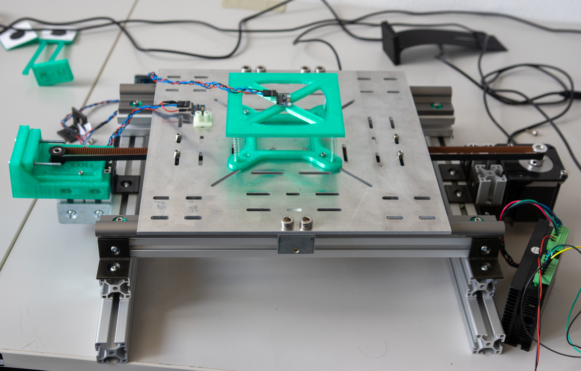
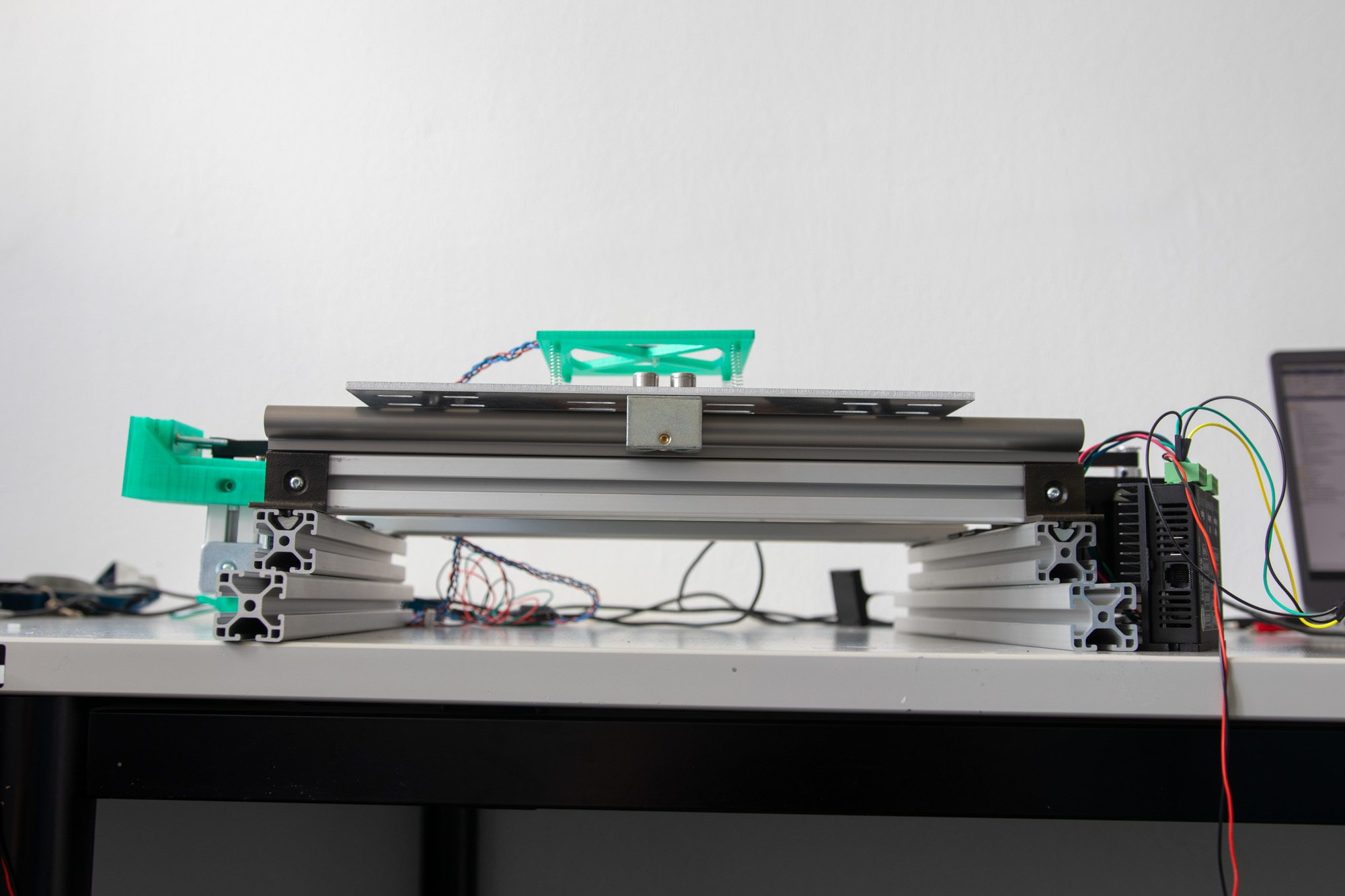
Complete table#
Assembly of the electronics#
The micro controller, driver and motor need to be connected in a specific way to operate properly. The DM542-driver has inputs for DIR and STEP signals which need to be connected to the micro controller, outputs to the motor and it also needs to be connected to the power supply. The DIR- and PUL- inputs need to be connected to GND (0 V), DIR+ and STEP+ are connected to pins G4 and G23 respectively. This could be changed in the ESP32-software if desired, but that includes re-flashing the software onto the controller. The motor is connected to the NEMA23 according to this, where the colors of the leads of the motor are indicated (B- - blue, B+ - red, A- - green, A+ - black). The power supply is directly connected to the driver, where the red connector is V+ and the blue connector is GND.
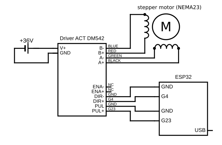
Wiring of ESP32, NEMA23 and DM542#
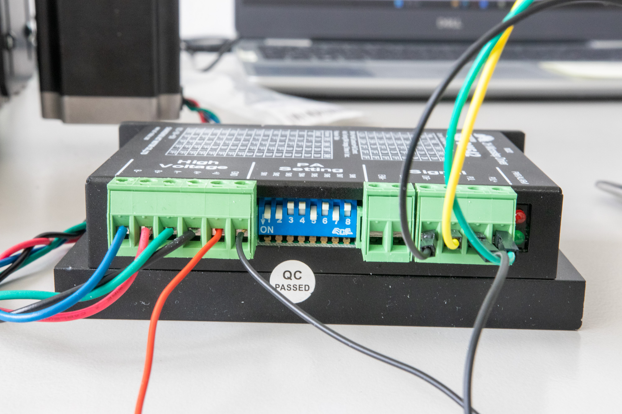
Stepper driver settings#
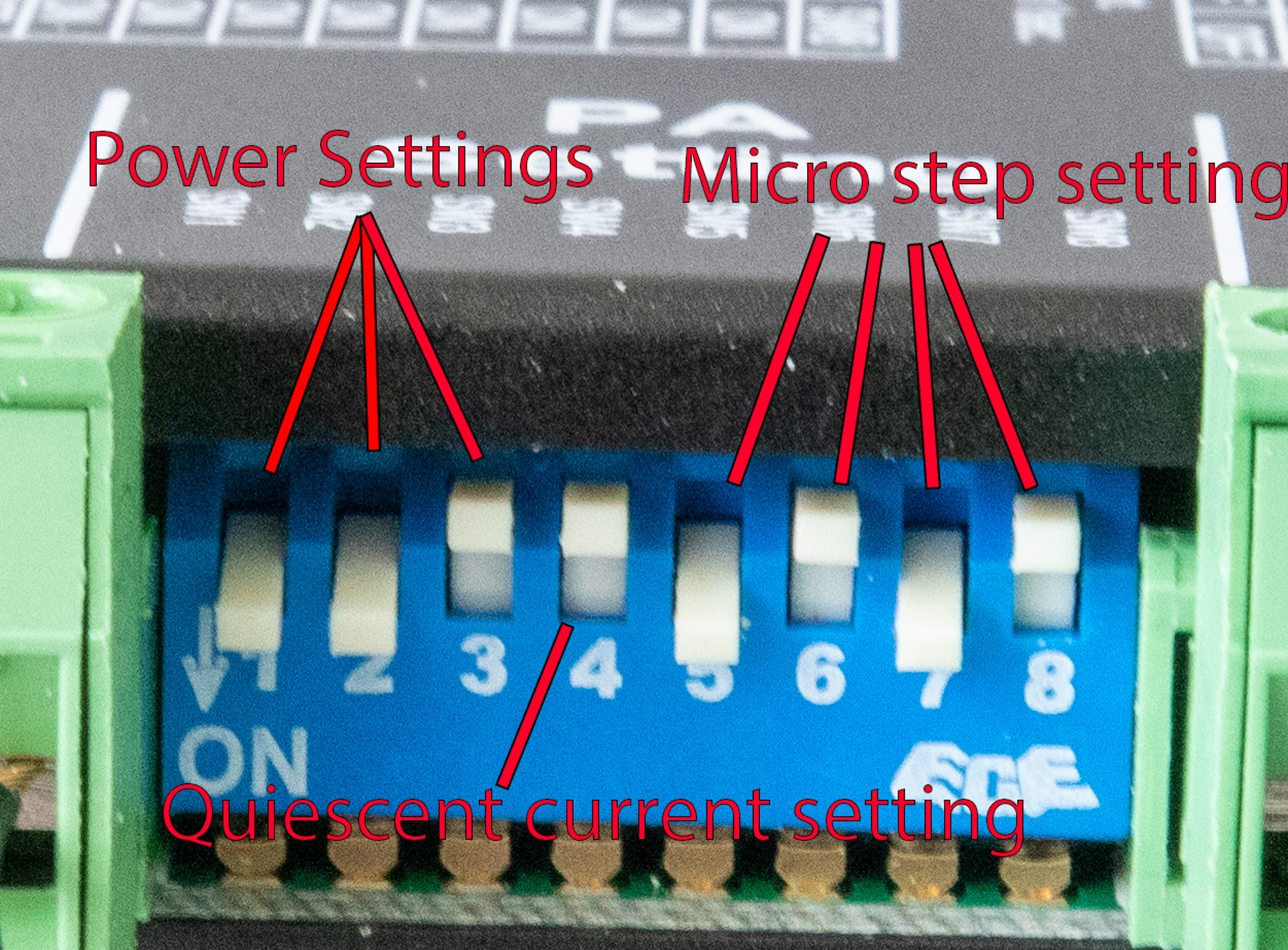
Stepper driver settings (close up)#