
Functionality#
This section describes the general functioality of the table, including the controller firmware, Marv-Code and overview of the serial communication. We refer to the motor-code as Marv-Code, because it works similarly to G-code and Marvin “Marv” Banse was mostly responsible for its definition and implementation.
Overview and Introduction#
The shaking table is equipped with a control system to apply any single-axis displacement to the plate. The software generates or loads a discretized time-displacement signal, translates it into Marv-code for the motor, and sends it to the microcontroller via the serial interface. The code is then saved on the microcontroller such that the experiment can be started or restarted at any point. The processing of Marv-code as well as the interface with the microcontroller and the microcontroller itself make up the control system.
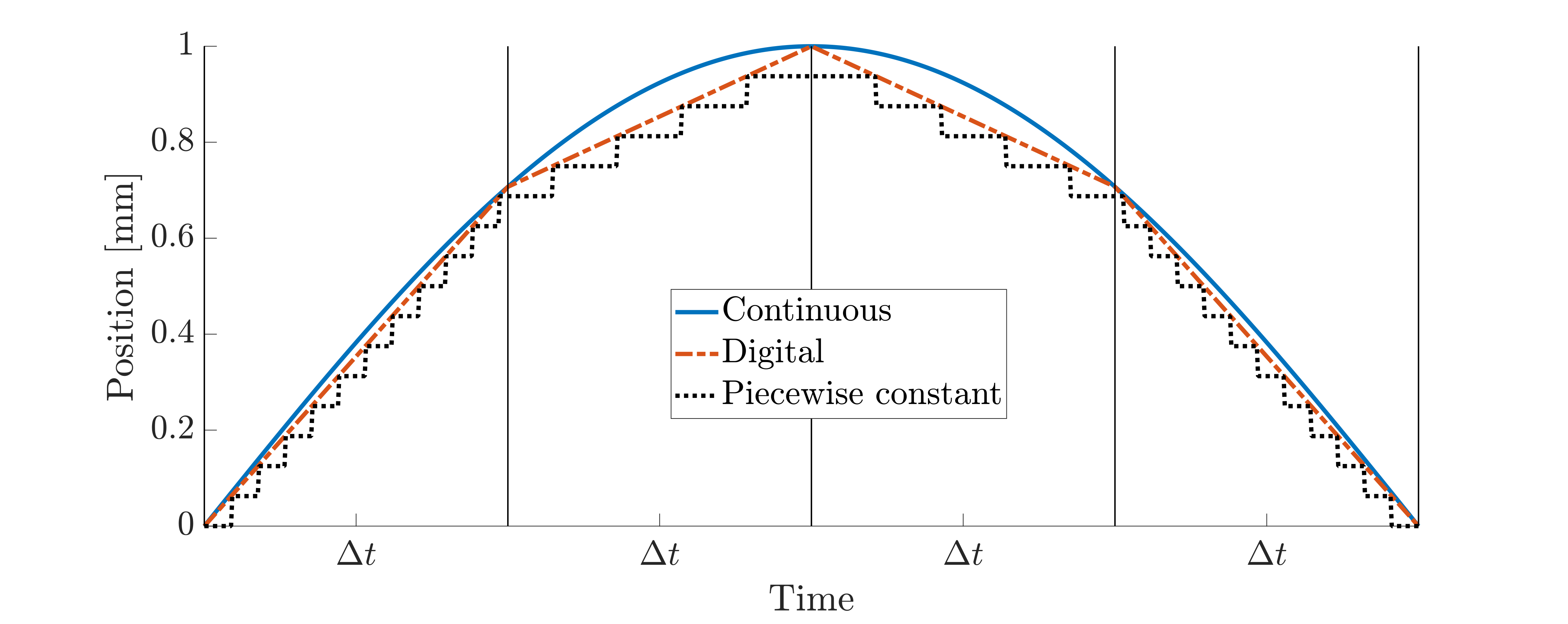
Starting from a (theoretically) continuous displacement signal \(x(t)\) as described in the signal generation description there are two discretization layers needed for the motor control. The process is illustrated in the figure below, where the discretization process is greatly exaggerated for the sake of clarity. The continuous signal (solid blue line) is first discretized to obtain the digital signal (dashed red line), i.e. an array of size \(n_t\) consisting of numbers that specify the desired positions in a fixed interval \(\Delta t\). The second discretization occurs in the microcontroller to determine the stepping rate of the motor. Programmatically, the microcontroller is given the list of positions and the time discretization \(\Delta t\). Therefore, the firmware can linearly interpolate between the positions in time, where the distance between two positions determines the desired velocity and therefore the stepping rate. Note that the motor is only able to move one step at a time which results in a piecewise constant position signal (dotted black line). However, choosing \(\Delta t\) small enough results in a good accuracy of the movement. We found that using \(\Delta t = 5\ \text{ms}\) gives good results without pushing the limits of the microcontroller’s speed.
Microcontroller firmware#
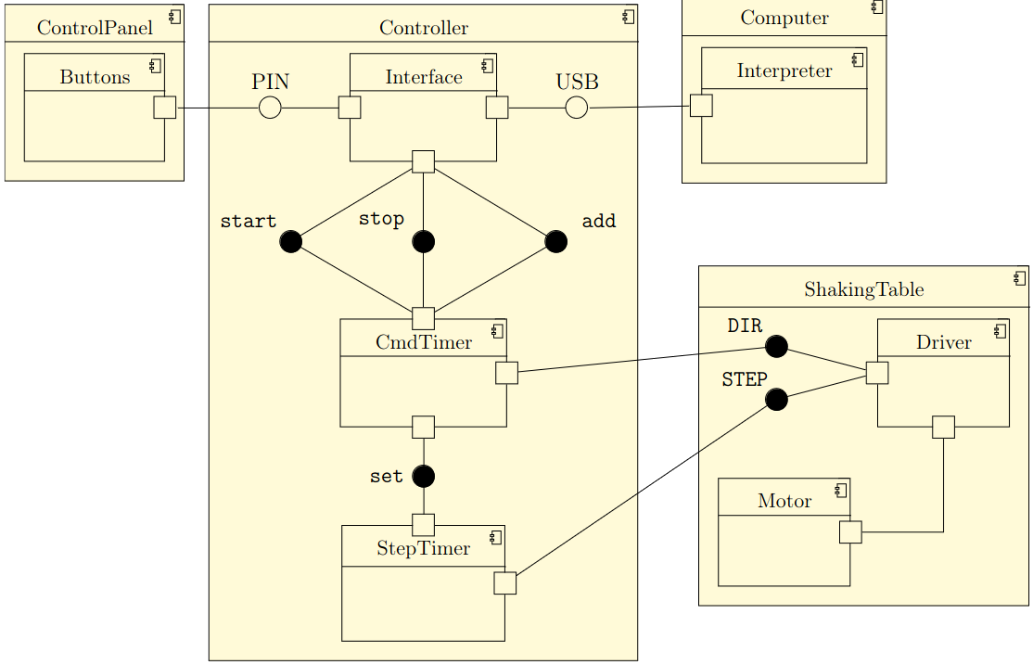
The microcontroller’s program (called firmware) is the interfacing element between the software, an optional operator, and the motor. As shown here, the firmware provides two interfaces:
USB: A serial interface, which processes readable commands and floating numbers in ASCII. An exemplary sequence of commands is shown in the example below.
PIN: A set of electrical lines to trigger certain signals. These pins allow the installation of an optional control panel with buttons to start, stop and adjust the table, or optional limit switches to protect the hardware.
    # clear previous positions from memory
    reset
    # set steps per mm
    set spmm 160
    # set instructions per second
    set rate 1
    add 10 # add positions (in mm)
    add 0
    add -10
    add 0
    start # start the experiment
The commands and signals are processed by the Interface component of the firmware. There are three classes of commands to differentiate:
Configuration, beginning with
setDefinition of the experiment, beginning with
addActions, like
startorstop.
A full list of supported commands is listed here. A previous version of the motor control firmware used G-code, which is a standard already existing and most widely used in 3D printers and CNC machines. Thus, G-code could be used to communicate with the motor. However, we found that there is some overhead (such as acceleration limits) in the implementation of G-code itself that is not needed for the shaking table but interferes with the accuracy of the timings. We therefore introduced Marv-code, which is a similar but slimmer approach. It provides the most important settings (such as steps per millimeter, the discretization length \(\Delta t\)) and a list of positions to the controller. It is possible to change the settings without the need to interfere with the controller firmware itself. This process is independent of the used programming languages and operating systems, as long as they can interface with a serial port (i.e. a USB port). The firmware is designed to work with any kind of stepper motor/driver combination that uses the same STEP / DIR interface (A4988, DRV8825, TMC2208, TMC2209, DM542, etc.) and therefore also with a wide range of stepper motors.
Displacement of the table is applied by the motor through a sequence of discretized positions for a series of constant elapsed times between two consecutive positions \(\Delta t\) during the whole signal. The firmware uses two so-called timers to drive the motor correctly. The first timer, CmdTimer, is configured to trigger at a static rate during the experiment. This rate is received by the Interface (c.f. rate command).
The Interface sets up the CmdTimer and gets activated at a start command. Each time the CmdTimer triggers, it loads the next imposed position of the experiment and calculates the velocity and direction of the motor necessary to reach it. Then the CmdTimer triggers again.
The CmdTimer also sets the drivers’ DIR pin according to the required direction.
The calculated velocity multiplied by the step resolution (steps per millimeter) gives the rate of the so-called StepTimer to trigger.
Thus, each time the CmdTimer processes the next position, it reconfigures the StepTimer.
The StepTimer generates a rectangular signal and sets the STEP pin of the driver accordingly.
Thus, Marv-code allows for the precise description of arbitrary, uniformly sampled signals directly via the serial interface. There is no need to re-upload the controller firmware for a new experiment. Furthermore, changes in the hardware setup are fully described by the spmm command.
Basic overview of the firmware#
Microcontroller interface#
To upload the signal to the motor, it is translated into microcontroller-readable code via a simple interpreter that takes the pre-calculated time-displacement signal and generates a sequence of strings to be sent to the controller via serial. To ensure safe operating conditions, for each new experiment i.e., each time we load new data, we reset the current experiment data and prescribe the steps-per-mm setting and the rate (see the reset, set spmm and set rate commands in the Marv-code example). Afterward, the interpreter writes the desired positions as a sequence of add instructions. Note that we do not need to prescribe the time since the signal is discretized uniformly. The rate is given by rate n i.e., the controller uses n positions per second.
The start command can be sent simultaneously or separately without sending all of the previous commands again, e.g. to make sure that the table is safe to operate before starting the experiment. The experiment can also be interrupted at any point using the stop command, or, after the experiment is finished, restarted by sending start again. All generated data such as input signal, Marv-code, and parameters can be stored on disk to re-run experiments that were previously generated. This is currently realized with a custom class which also makes handling of all settings and parameters easy.
Any programming language or framework that can use serial interfaces can communicate with the controller, which makes this approach very versatile. Already existing methods for signal generation can be employed without rewriting functions for different software packages or operating systems. Although we only provide a code base and interpreters for MATLAB and Python, and the general functionality is the same if another software environment is chosen. We therefore expect that translating the existing implementation to other languages is straightforward.
Pre-/post-processing and restrictions#
Input harmonic and stationary random signals are generated with the algorithms introduced in the signal generation section. However, the input signals are not restricted to these algorithms. Any signal could be considered. For instance, we could generate non-stationary signals including frequency sweeps or increasing amplitude, or load pre-recorded data from vibration experiments or earthquakes.
The only restriction we impose is that the signal is discretized with a constant sampling rate (i.e. \(\Delta t = \text{const.}\)). Besides, the desired amplitudes and frequencies should not exceed safe operating conditions, especially when no limit switches are used. To avoid sudden acceleration spikes, it is advised to use the linear ramp up and ramp down shown here whenever possible.